The simulation environment consists of the fluid container that in 3d space is a 3D boundary box defining the area in which the fluid can exist and it is divided into uniform cells called voxels. A voxel represents one unit and it can store the values of the fluid like velocity, density, position and it has two states. It can be either free, and this means that the fluid can move, or solid and this mean that the cell is occupied. In order to have good simulation results, the internal and external boundary conditions should be well defined.
There is a wide range of boundary conditions types that permit the flow to enter (inlet) and exit (outlet) the simulation environment. The boundaries can be either external or internal. The external boundaries are referred to the environment around the design (fluid container) and for this thesis purposes are defined as a cube where the two opposites sides behave like inflow and outflow boundary, having a constant flow of incoming velocity and density and the other two were not considered as external boundaries trying to exhibit the wind tunnel effect (Chronis et al., 2011). The internal boundaries referred to the object inside the simulation environment (buildings on both sides of a passage). Concerning the internal boundaries, whether a cell is occupied or not heavily depends on the object but it should satisfy the requirement that at least two consecutive cells of the fluid domain are needed in order to counteract the velocity and density of the fluid on the two sides of the object. (Chronis et al., 2011) (Fig_32)
The dimensions of the buildings are 32m x 7m x 19m (Length x Width X Height) and each building is divided into 4256 voxels. Furthermore, the dimensions of the space (3D passage) between the parallel buildings are 32m x 10m x 19m and it is divided into 6080 voxels. The experiments carried out which will be explained in following section, exhibited that the most problematic areas are the corners of the first building and the leeward side of the first building as well. The diagram below represents the areas that they will be taken into account in the GA step that is followed. (Fig_33)
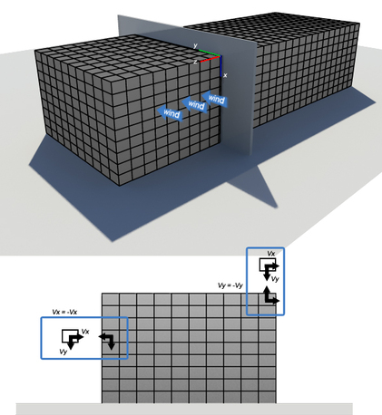
Fig_32
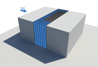
Fig_33
