As the whole FFD environment used is now described, next step in this methodology section was to actually recreate the tunneling effect into our simulation environment. Many experiments took place at this stage, which will be explained later on, but target was to try and mimic the phenomenon as accurately as possible. A cube of 60x100x40 (240000 voxels) dimensions was created as the FFD simulation basis. The two opposite vertical sides of the cube were not considered as external boundaries and the one was chosen as the inflow side of the wind with the other one acting as the outflow to model an outdoors environment. The buildings were modeled as solid internal boundaries to be able to act as solid obstacle to wind flow. After quite a few experiments concerning wind speed, wind direction, building layout and passage width, a final layout that was accurately representing the phenomenon was chosen as shown in the diagram below (Fig_34). For visualization purposes apart from the 3D perspective of the environment, section cuts were also created to try and understand wind behavior, as it is very computationally intensive to visualize wind particles in a 3D environment.
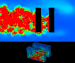
Fig_34
